Leave Your Message

How to Choose the Right Standoff Insulator?

Choosing the right Standoff Insualtor is not a simple voltage-matching exercise. The component must survive electrical stress, mechanical loading, heat, moisture, and contamination. A clean laboratory rating may not represent a dusty factory, coastal cabinet, or outdoor switchgear assembly.

Andrew R. Hileman, a respected authority on insulation coordination, emphasized that insulation must be selected for real system stresses, not voltage alone. That principle remains practical today. A designer should examine working voltage, transient overvoltage, creepage distance, clearance, dielectric strength, and tracking resistance. Material choice matters too. Epoxy, porcelain, and engineered polymers behave differently under heat and surface contamination.

Look closely at the installation.

A small mounting error can reduce clearance. A sharp metal edge can create local electric-field concentration. Excessive tightening can crack a ceramic body or deform a polymer part. These details are easy to overlook during a drawing review. They become expensive when failure causes arcing, downtime, or damaged equipment.

The correct Standoff Insualtor should also match its enclosure, conductor arrangement, fasteners, and maintenance conditions. Check the manufacturer’s test data, dimensional drawings, temperature limits, and recommended torque values. Do not rely on a catalog headline alone.

There is room for reflection here. Many selection guides focus heavily on rated voltage. That approach is convenient, but incomplete. Real reliability comes from combining verified data with honest field assumptions. When conditions are uncertain, a qualified electrical engineer should review the design before production.
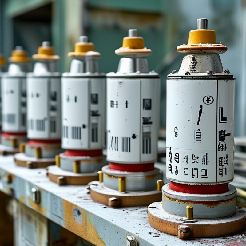
How to Choose the Right Standoff Insulator?

What Is a Standoff Insulator and How Does It Work?

How to Choose the Right Standoff Insulator?

What Is a Standoff Insulator and How Does It Work?

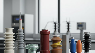
A standoff insulator supports an energized conductor while keeping it away from grounded metal. It creates electrical clearance and adds mechanical stability inside panels, switchgear, busbar systems, and outdoor equipment. Its body may use ceramic, glass, or a molded polymer. A threaded insert or mounting base secures it to the enclosure.

The working principle is simple. The insulating body blocks current from reaching the support structure. Its shape also controls clearance through air and creepage along the surface. Moisture, dust, salt, and heat can reduce this protection. That detail is easy to underestimate. The U.S. Department of Energy’s 2023 National Transmission Needs Study reports that over 70% of transmission lines are more than 25 years old. Aging equipment increases the value of careful insulation inspections and replacements.

Selection should begin with system voltage, operating temperature, impulse voltage, and pollution exposure. Check the required creepage distance, not only the overall height. Measure the busbar load and select a suitable mechanical rating. A loose fastener can create vibration, tracking, or uneven stress. Use a calibrated torque wrench during installation. The International Energy Agency reported in 2023 that more than 80 million kilometers of grids may need new construction or replacement by 2040. That expansion will demand consistent, documented component choices.

A catalog match is not always a safe match. I would also inspect condensation, mounting space, and cleaning access. Sometimes, the overlooked detail is the real failure point.
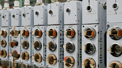
How to Choose the Right Standoff Insulator?

A standoff insulator electrically separates a conductor from a mounting surface while also providing mechanical support. The best choice depends on dielectric strength, operating temperature, creepage distance, clearance, and mechanical load.

Typical dielectric strength: Higher values generally indicate greater resistance to electrical breakdown in a uniform, dry material sample. These representative values are for material comparison only; the final standoff rating must also account for geometry, humidity, contamination, altitude, temperature, and applicable safety standards.

Which Electrical and Mechanical Requirements Must Be Defined?

How to Choose the Right Standoff Insulator?

Choosing a standoff insulator starts with defining its electrical duty. Record the working voltage, transient voltage, frequency, and expected leakage current. Clearance protects against air breakdown, while creepage controls surface tracking. Both distances depend on pollution, humidity, altitude, and insulation material. A design tested in a clean laboratory may behave differently near dust or condensation. Specify dielectric withstand voltage and insulation resistance, then verify them under realistic conditions. Do not rely only on a catalogue rating.

Mechanical requirements deserve equal attention. Define the supported weight, bending force, vibration level, and mounting direction. Include thread size, hole tolerance, installation torque, and available space. Temperature cycling can loosen hardware or create stress between dissimilar materials. Check tensile and compressive strength, but also inspect the weakest section near the mounting thread. In field reviews, small alignment errors often caused more trouble than the calculated load. A perfect specification is rarely possible; practical tolerances must be stated clearly.

Tips: Write a requirement sheet before selecting a part. Measure the actual clearance around terminals. Ask for test conditions, not only test results. Confirm temperature limits, flammability performance, and material compatibility. If vibration is present, test an assembled sample with the intended hardware. Recheck creepage after cleaning, coating, or enclosure changes. One detail is easy to miss. Keep revision records, because an unnoticed dimensional change can affect both electrical safety and mechanical stability.

How Should Voltage, Load, and Environmental Conditions Be Compared?

Choosing the right standoff insulator starts with comparing voltage, mechanical load, and surroundings together. Voltage is the first filter, not the final decision. Compare the insulator’s continuous rating with the system’s maximum operating voltage, including temporary overvoltage. Check creepage and clearance distances against the installation altitude and pollution level. A dry indoor cabinet needs less protection than a dusty outdoor switchgear enclosure.

Load requires equal attention. Identify the conductor’s weight, tightening force, vibration, and possible short-circuit stress. A ceramic or polymer insulator may meet the voltage requirement yet fail under excessive cantilever force. Review the manufacturer’s mechanical ratings, then apply a suitable safety margin. Do not treat a catalog maximum as a normal working target. Measure the mounting surface, bolt pattern, and conductor position before ordering. Small alignment errors can create large side loads.

Environmental conditions can quietly change the result. Consider temperature swings, moisture, salt spray, ultraviolet exposure, chemicals, and ice. Polymer surfaces may perform well outdoors, but contamination and aging still require inspection. Ceramic bodies resist heat effectively, although impact damage can be less obvious. Field engineers should document test conditions and revisit assumptions after installation. A neat spreadsheet can still mislead. For example, a lightly loaded insulator in a clean laboratory may face severe vibration beside a motor. Compare real service conditions, not only nominal ratings. When uncertainty remains, testing a representative assembly is often wiser than selecting the cheapest margin.

How to Choose the Right Standoff Insulator? - How Should Voltage, Load, and Environmental Conditions Be Compared?

Insulator Type / Material Typical Voltage Suitability Typical Mechanical Load Approximate Operating Temperature Environmental Resistance Recommended Applications Important Selection Limitations
Polycarbonate
General-purpose molded standoff
Generally suitable for low-voltage assemblies, commonly below 600 V when the creepage, clearance, and insulation system are properly designed. Low to moderate; appropriate for lightweight circuit boards and enclosed control assemblies. Typically about -40°C to 115°C, depending on grade and continuous-load requirements. Good impact resistance and suitable for indoor use; prolonged UV exposure may require a UV-stabilized grade. Control panels, electronic enclosures, low-voltage PCB mounting, and light-duty assemblies. Not the first choice for high voltage, severe heat, strong solvents, or high sustained mechanical stress.
Nylon
Engineering-plastic standoff
Commonly used in low-voltage equipment; voltage suitability depends strongly on moisture absorption, geometry, and material grade. Low to moderate; glass-filled grades provide greater stiffness and pull-out resistance than unfilled grades. Typically about -40°C to 85°C for continuous service, with higher-temperature grades available. Good abrasion and impact resistance, but absorbs moisture, which can reduce dimensional stability and insulation performance. General electronics, appliances, low-voltage control equipment, and cost-sensitive assemblies. Avoid relying on unsealed nylon where humidity, condensation, or precise electrical spacing is critical.
Glass-Filled Thermoset or Thermoplastic
Reinforced insulating standoff
Suitable for low- to medium-voltage assemblies when designed with adequate creepage and clearance; commonly selected for improved rigidity. Moderate to high; reinforced construction reduces deflection under board, busbar, or terminal loads. Typically about -40°C to 130°C, depending on resin system and reinforcement. Good dimensional stability, stiffness, and resistance to many industrial environments; resin compatibility must be checked. Power electronics, switchgear interiors, busbar supports, and equipment exposed to vibration. May be more brittle than unfilled plastics; verify impact strength and mold-parting or fiber-orientation effects.
PTFE
High-chemical-resistance standoff
Useful for low- to medium-voltage insulation where low dielectric loss and chemical resistance are important; exact voltage depends on wall thickness and geometry. Low to moderate; relatively soft and prone to creep under continuous compressive or clamping loads. Approximately -200°C to 260°C in suitable applications, although mechanical strength decreases at elevated temperature. Excellent resistance to moisture, oils, and many chemicals; good outdoor weathering performance. Chemical-processing equipment, laboratory instruments, high-temperature wiring, and low-loss RF assemblies. High cost, low stiffness, and cold flow make it unsuitable for many high-load mounting points.
Epoxy-Glass Composite
Rigid high-performance standoff
Often selected for medium- and high-voltage assemblies; actual working voltage must be established from insulation coordination, creepage, clearance, and testing. High; suitable for rigid support of busbars, terminals, and heavier electrical components. Commonly about -50°C to 155°C, depending on resin formulation and certification requirements. Good electrical insulation, stiffness, and dimensional stability; moisture absorption and surface contamination still need consideration. Switchgear, power supplies, transformers, motor controls, and industrial power distribution equipment. Inspect for cracks, voids, surface tracking, and damage from excessive tightening or impact.
Technical Ceramic
Porcelain or alumina-based standoff
Well suited to medium- and high-voltage applications because of high dielectric strength and excellent resistance to tracking when properly designed. High compressive strength, but limited tolerance to shock, tensile stress, and uneven mounting loads. Often suitable from below -50°C to above 200°C; the mounting hardware and thermal cycling usually determine the practical limit. Excellent resistance to heat, UV, moisture, and many chemicals; surface contamination can still reduce flashover performance. High-voltage equipment, RF systems, furnaces, outdoor electrical assemblies, and high-temperature installations. Brittle and relatively heavy; avoid bending loads, sharp impact, and uncontrolled thermal shock.
Silicone Rubber
Flexible outdoor standoff or insulating support
Suitable for low- to medium-voltage insulation where flexibility, sealing, and outdoor tracking resistance are needed. Low to moderate; appropriate for vibration isolation and flexible sealing rather than heavy rigid support. Typically about -50°C to 180°C, depending on compound and continuous-service conditions. Excellent weathering, ozone, and UV resistance; hydrophobic surface behavior can help in damp outdoor environments. Outdoor electronics, vibration-prone equipment, sealed assemblies, and cable or terminal insulation. Not suitable where high rigidity, sharp-edge resistance, or high compressive load retention is required.
Selection guidance: Compare the required continuous working voltage—not only the short-duration test voltage—with the insulator's creepage distance, clearance, pollution level, altitude, and surface condition. Confirm mechanical ratings for the actual load direction, tightening torque, vibration, and temperature. The ranges above are typical material-level guidance; the final rating must be verified against the specific part design, applicable safety standard, and manufacturer's test data.

Which Materials and Mounting Designs Suit the Application?

How to Choose the Right Standoff Insulator?

Material selection should follow the application’s electrical, thermal, and environmental demands. Epoxy and phenolic compounds provide strong mechanical support and reliable dielectric performance. Silicone and other polymeric materials perform well outdoors because they resist moisture and surface tracking. IEC 60112 testing measures comparative tracking index, or CTI, which helps engineers compare insulation under contamination. Higher CTI values usually support safer designs in humid or polluted locations. However, CTI alone cannot predict field life.

Mounting design matters just as much. Threaded standoffs suit compact busbar assemblies and allow controlled spacing during installation. Slotted or adjustable mounts help compensate for fabrication tolerances, though they may introduce movement under vibration. Compression should be distributed evenly. A sharp washer edge can create local stress and reduce long-term reliability. IEC 60664-1 requires designers to consider clearance, creepage, pollution degree, and impulse voltage. Those dimensions often change more than expected.

Market data also reflects this shift. The MarketsandMarkets 2023 report estimated the electrical insulation materials market at about USD 3.6 billion, with growth toward roughly USD 5.1 billion by 2028. That growth does not make every polymer suitable. I would still request thermal-aging results, flammability data, and torque guidance before approval. A design that looks strong on paper may fail after heat cycles, dust, and repeated maintenance. That is the uncomfortable part. Testing the assembled hardware remains essential.

How Can the Selected Standoff Insulator Be Verified and Maintained?

Verification begins with the installed environment, not the catalogue sheet. Check the standoff insulator’s material, voltage rating, creepage distance, and mounting torque. IEC 62217 links polymeric-insulator performance to design, material, and environmental testing. A correct voltage rating alone is insufficient.

Use a calibrated insulation-resistance tester at the manufacturer’s specified test voltage. Record temperature, humidity, readings, and test duration. Do not invent a universal pass value. Moisture and contamination can reduce readings sharply. CIGRE Technical Brochure 555 identifies pollution, wetting, and surface deposits as major influences on outdoor insulation performance. Inspect for hairline cracks, tracking marks, chalking, loose hardware, and discolored metal. Photograph each defect. Small marks deserve attention.

Maintenance should follow operating conditions. In dusty or coastal locations, inspect more frequently than in clean indoor cabinets. Clean with an approved method that will not damage the insulating surface. Never scrape deposits with a metal tool. Confirm torque after cleaning, but avoid crushing brittle ceramic or polymer parts. NETA’s Maintenance Testing Specifications emphasize documented test results, visual inspection, and condition-based decisions. That approach is practical, but not perfect. A clean insulator can still hide internal damage. Recheck after abnormal heating, short-circuit events, flooding, or equipment relocation. Compare every reading with previous records, not only with a single limit. Fresh data often reveals gradual deterioration earlier.